There are growing demands on the equipment operating in the production line. Seen from a perspective, the criteria for selecting equipment are becoming more and more complicated every year and purchasing decisions are becoming more and more difficult.
The quality of manufactured products and, above all, the efficiency of processes depends mainly on the technical capabilities of machines and equipment used in production. The choice of production or service machines in the realities of the company’s economy is determined not only by the usable qualities of the equipment, but also, to a large extent, by the quality and performance to price ratio. Other aspects considered when purchasing production equipment include after-sales service (service, warranty), availability of equipment and the history and perception of the brand by customers. Therefore, those deciding on purchases are faced with the difficult task of combining technological, financial and logistical choices in an intricate equation.
WHAT EQUIPMENT DO WE NEED?
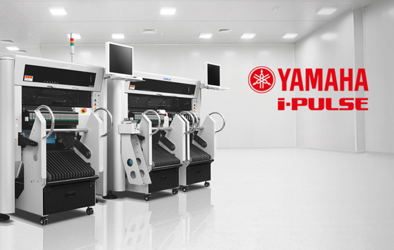
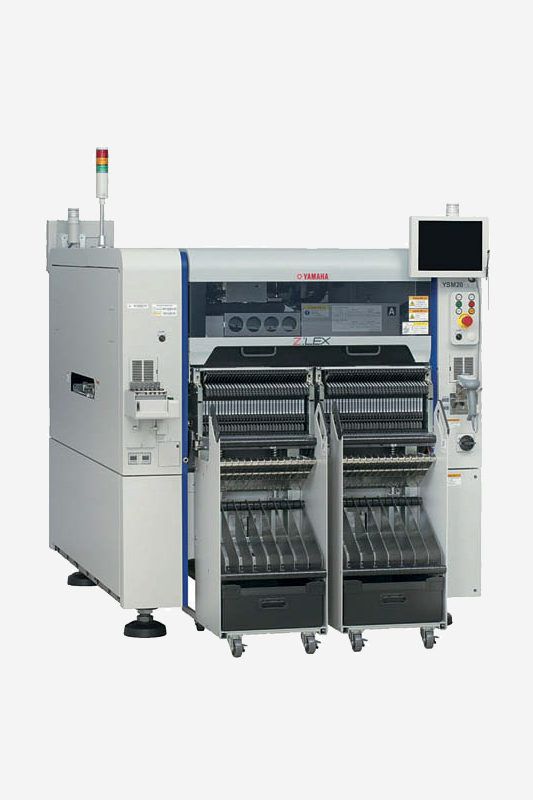
Configuring the line for assembling SMD elements starts with choosing a pick&place machine. In case of Yamaha devices all models are characterized by high assembly precision, capability to mount components of different sizes and shapes (also irregular) and high efficiency. The maximum number of components that can be mounted per hour is 90,000 (compliant with IPC-9850). Such performance is achieved by the YSM20 (Z:LEX), which allows the production of electronic packages containing a very wide range of components. The device is equipped with new linear motors and an improved control system for their operation.
The weight of the mounting head has also been reduced. The result is an increase in placing speed and a 25% increase in productivity compared to the YS Series. The modular design of the machine allows it to use two types of interchangeable heads – HM with 10 nozzles, FM with 5 nozzles or both.
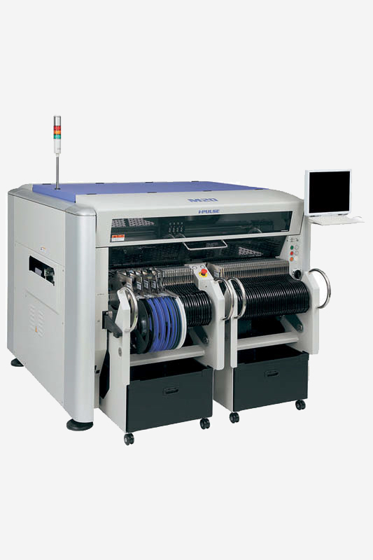
The first one supports components up to 15 mm high and includes a scanning camera. The FM head is equipped with a clamping force control system and can stack a wider range of components up to 28 mm high. Both heads provide the ability to pick 03015 components, 56% smaller than the popular 0402. Of course, Yamaha’s range of devices is not limited to one of these models. Another series of devices, the I-Pulse, provides an assembly capacity of 23-45 thousand components per hour. They support components from 01005 and are capable of handling PCBs up to 1830×510mm.
AUTOMATIC 3D INSPECTION
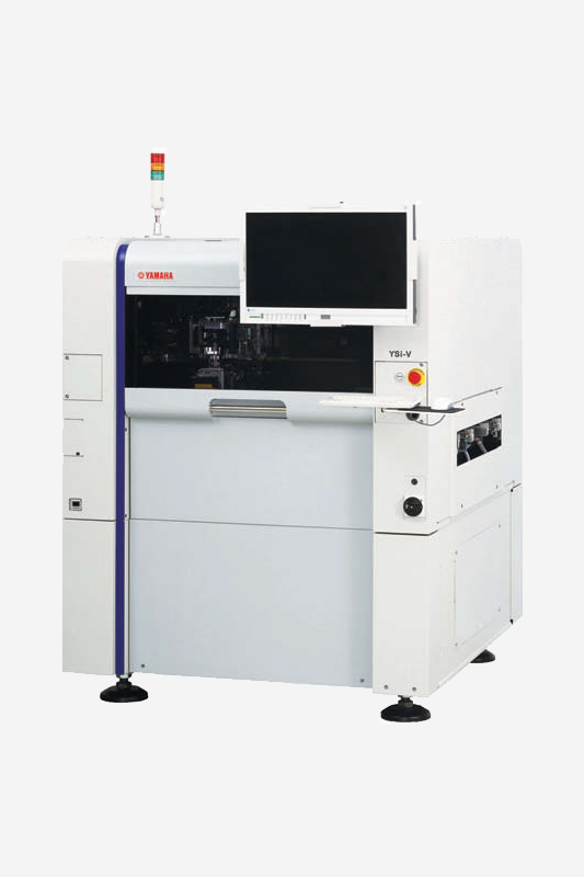
The reliability of PCB packages produced is often linked to the market value of the end product. With today’s miniaturisation, manufacturers ensure high quality by means of automatic inspection systems. AOI Yamaha’s AOI YSi-V was developed as an in-line system with the possibility of quick inspection also in dual-line production.
In order to build a market advantage over the other systems, the Japanese manufacturer has implemented AOI integration with other Yamaha systems (YS12, YS24, YSM20 and others) to provide real-time feedback of inspection results to the machine.
Thanks to the software integration, the machine receives information on errors detected by the AOI, allowing quick corrections to be made as early as at the component installation stage. This minimises the number of defective products, thus increasing productivity while maintaining a smooth production process. The system is equipped with a 12-megapixel 2D inspection camera, which is a basic function of every AOI.
New feature is 3D and 4V inspection. The former controls, among other things, the height and angle of the component, i.e. defects that unfortunately 2D inspection may not detect. The second function is a novelty in the system – 4-way angle camera. The 4V function makes the camera captures images of the component from four different perspectives. Many details are checked, e.g. angle of tilt, lead bend. The images from these views are stored in a database and allow additional inspection without removing boards from the line.
SOLDERING OVENS
An important process that determines the quality of production is the correct and repeatable soldering in the reflow oven. Such features has the GRP 1385 EVO consisting of five zones, which is equipped as standard with a stainless steel mesh conveyor of maximum width of 400 mm. Optionally it can be equipped with additional edge transport with central support. In addition, the device has a built-in profile meter, which ensures that the thermal soldering profile is created precisely for each application. This solution is not standard in competing devices of this class.
The optional SMEMA communication application allows you to set up the device in the production line. The German production company SMT Wertheim, introduced a new concept of working environment in reflow soldering systems, which aims to minimize process costs by maximizing the use of resources. It is based on the design of the devices and their work cycle, adjusted to the lowest possible energy consumption, intelligent use of nitrogen and minimization of maintenance expenses.
Every Wertheim SMT is equipped with Power Nozzle technology – a special nozzle system that uses a high-performance fan while maintaining a low flow speed. The improved nozzle geometry allows for excellent process gas transfer resulting in improved quality and energy savings.
The double absorption chamber system provides a convincing solution for cleaning the process gas and eliminates additional cleaning equipment. This ensures minimal downtime (thanks to disposal through continuous waste recovery) and high process efficiency.
Narrow and tight PCB entries reduce gas release to a minimum, thus reducing gas consumption, energy costs and providing a clear temperature separation in the zones, each zone can be adjusted separately. Another advantage of the Power Nozzle system is the excellent temperature distribution in all heating zones.
VACUUM REFLOW SOLDERING
The presence of voids in the soldering process is a pain for every quality controller and must be taken into account in production. These voids can adversely affect the reliability of an application on a PCB, weakening its electrical, mechanical and thermal integrity. The reasons for the formation of voids during reflow and wave soldering are not always easy to define and concern both lead free and lead solder connections. They are taken from crystalline flux inclusions, gas and moisture bubbles coming from components and their housings.
They are also caused by gas escaping with non-polymerized photoresists of the soldering mask and air inclusions below the components due to imperfect printing or pad design’.
Negative effects of voids on product quality include reduced heat dissipation from components or soldering point structures, reduced stability of the soldering connection, reduced performance of components in high frequency and high power applications, and increased soldering problems (bridging, soldering with splinters, e.g. in BGA). A number of possibilities to reduce the void phenomenon can be identified, however, a process based on constant vacuum is currently the most beneficial and developed in modern production equipment. The German manufacturer, developing constant vacuum technology, has developed the Vacuum Plus N2 method, which aims to eliminate these problems in the reflow soldering process.
The requirements of the market inspired SMT Wertheim to create a technology based on vacuum principles, which was additionally introduced for economic reasons throughout the soldering process. There are other vacuum processes, but they are stop-and-go, less environmentally friendly, more expensive and cannot meet the more economically advantageous Vacuum Plus N2 method. The Vacuum Plus N2 vacuum module is a stand-alone unit that can be fully integrated into the reflow soldering system. As the presented reflow oven systems are also modular in design, the Vacuum Plus N2 module can easily be installed in an existing reflow oven.
The Vacuum Plus N2 is placed directly behind the peak zone (specific heating – flow) and can only be activated if necessary and the vacuum process is centrally controlled with an on/off option. During the continuous flow, the Vacuum Plus N2 module is automatically switched to vacuum and the PCB is exposed to the vacuum for a short time and then de-aerated. The voids in the soldering joints are reduced to an acceptable minimum during the process. The vacuum cycle time of the reflow soldering is 60 to 90 seconds.


